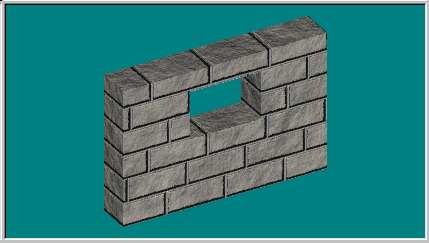

Making a wall with a window should be easy, right? Well, it isn't... if you don't know how. This tutorial is intended to show how splines are connected make a big difference to getting what you think you are modeling, by exploring a very simple case.
We are going to purposely make the first example not work right to start off this tutorial, mainly to point out beginner's mistakes. But if you follow along by creating the different example models in your version of Animation Master, you should begin to see how spline connections work and hopefully come to a better understanding when designing your model's splines (mesh). I recommend you do the two Basic Splinemanship Tutorials to familiarize yourself with the toolset of AM. Assuming you have done that, then...
OK, first we will draw a 2 point spline and extrude it in the front view. Select all the CPs and whack "peak." Now we have a flat wall, and a test render will show it. Select all the CPs again and extrude in the Z direction, do another test render to show your new 3D wall. Kewl....
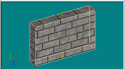
Now we want a window to cut through the wall, so here goes. We know a connected 4 point spline won't render (as we learned in the Basic Splinemanship tutorial) so we draw a connected 4 point spline in the middle of the wall, and connect it to the 4 corners of the wall with 2 point splines. OK, we see some splines are starting to curve so we peak the offending points. In wireframe mode everything is looking good, just the way we envisioned it. BUT, in a test render... no window! (Newbie's immediate reaction is that it must be a bug.)

OK, why no window? And just as important, how do we fix it?
If you come from a polygonal background, you're first thought would be Boolean cutter, so lets try that first. Delete all the "window" CPs, and copy & paste all the CPs that make up the wall, then scale it down on the X & Y and scale it up a tad in the Z using the scale manipulator. It should look something like this... (I exaggerated the Z scale for demonstration purposes, all you need to do is make sure the surface of the "window" box is extended past the surface of the "wall" box.)
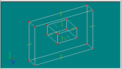
In AM to get a Boolean operation we must assign CPs to some bones. So, select the CPs that make up the window, whack the hide key, switch to the bones mode, add a bone & assign the CPs to it. Then on the properties panel for that bone click on "Boolean Cutter" checkbox. Unhide and test render... Ratz!!! Still no window! What the heck is going on here? (I said we were going to purposely make our first example not work, remember that?) OK, we need a second bone, so this time select the CPs that make up the wall portion and whack hide, go to the bones mode and add a new bone, then assign all those CPs to it. Now when you return to the modeling window, unhide and do a test render... we have a window in our wall! Yippee!! (If you need an image, look at the image at the start of the tutorial.)
OK, for a lot of modeling this method would work, however, if you were going to use the Toon renderer, then you won't get the thick outline lines around the cut out region that you would if you modeled a real hole in the mesh. I had you hide unwanted CPs before going to the bones mode to make it easier for you to assign them to a bone, in our little example it wasn't that important, but as you build denser meshes, you will find hiding unwanted CPs before switching to bones mode a good habit to get into. Also, although I didn't specifically mention it in this tutorial, naming groups will make CP selection easier with more complex models. Refer to my Basic Splinemanship tutorials for more data about that.
Now that we explored the Boolean method, let's go back to our very first example of a 2 point extruded spline, peaked and then extruded in the Z. We want to answer why that example didn't work, don't we? Delete the Boolean box and all the bones, we won't need them from here on out. All we should have left is our 3D wall with no window CPs. Here is the answer why making a window didn't work right away.

The wall renders, right? Well, those 4 corner CPs (painted green as well as the normal for this patch) will want to render all the time because they make up a valid rendering patch and that was our first mistake. What we really want is non-rendering spline(s) to start off with, and I will show you 2 different ways to do this.
Start a new model, so you can compare it to the first example we made. In the new model window, draw a non-rendering connected 4 point spline, peak all the points, and extrude it. Scale the extrusion a bit and do a test render. Golly! A window right of the bat! This is gunna be easy! Select the inner 4 CPs and extrude those in the Z direction. Then select the outer CPs and do the same thing. Select all and peak. Whoa! a 3D wall & window... Go to a side view and group select all the CPs that make up the front of the wall/window and copy, paste & translate them to same depth you extruded on the Z to make the back face of the wall. Done! There is no need to connect the back face at all (it should exactly match up if you have been using the snap manipulator to grid button and zero offsets on extrude, as explained in the earlier Basic Splinemanship tutorials). In the image below, notice there isn't a normal for the entire front face now, that's because of the way we connected the splines.
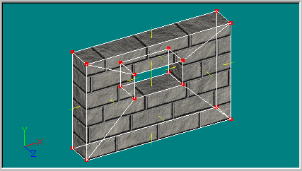
Why didn't we just select all the CPs instead of selecting them in two groups as above? OK, let's give that a shot. The paste buffer still has the front CPs in it, lets start another new model, and paste the front face of the wall into it. While it is still selected, hit extrude and translate the extrusion in the Z. Do a test render, if you are using the progressive render for your tests this model and the last one should look the same... BUT, if you do a final render on both models you will see internal patch artifacts on this one (now outlined in green). DOH!!!
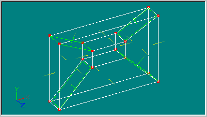
Are you starting to see that how splines are connected make a difference? If so, this tutorial is working, if not, go back to the beginning and start again...
This time we will make our window by extrusion, but this time we will plan ahead. Start a new model, draw a vertical 4 CP straight spline, snap to grid if needed. Select all and extrude it 4 times in the X. Select all and peak. Select the center most spline and break it in the middle. Bingo, a hole for our window. Why? because a 6 point patch will never render. Use the same method we used above to extrude the inner & outer CPs, again you can copy, paste the front wall to the rear if you need a back face.
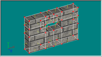
I am not saying these are the only ways to make walls with windows, we were actually inspecting the CP connections and how the connections can either give you something heretofore unexpected or something you really wanted. Knowledge is power... I hope this tutorial will help you in your more complex modeling. When you run into something unexpected, start looking at how your splines are connected maybe you will find a telltale clue.
If you learned something from this tutorial, please drop me an E-mail at Thanks
Jeff
This is an important step, I track the number of visits to "thank you"
notes, I need to know my time and my web space is well spent.
I have other tutorials linked from my hobby homepage. Give those a try too when you are ready.
Other Animation:Master tutorials can be found at Sherwood's Forest 